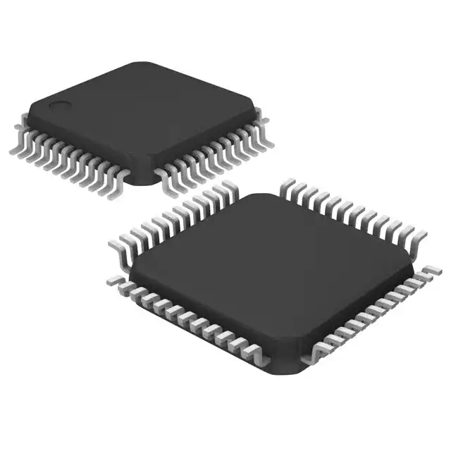
The DP8570AVX chip is a versatile real-time clock (RTC) integrated circuit that finds its application in various electronic devices requiring precise timekeeping and alarm functions. This chip is known for its reliability and extensive feature set, including programmable alarms, a watchdog timer, and battery-backed SRAM. However, like any sophisticated component, the DP8570AVX chip can present performance challenges that require careful troubleshooting to maintain optimal operation. This guide will walk you through the most common performance issues associated with the DP8570AVX chip and provide practical solutions to address them.period Digital integrated circuits Many adjustments have also been made, and the direction of product research and development has been reversed, in order to better meet the market demand. https://www.chipguest.com/
Understanding the DP8570AVX Chip
The DP8570AVX is an RTC module that offers advanced timing capabilities for systems requiring accurate date and time tracking. It can interface with microprocessors to provide timekeeping functions even during power interruptions, thanks to its battery backup feature. The chip is also equipped with additional features like programmable square wave output, time-of-day alarms, and watchdog timer functions, making it a critical component in many embedded systems.
Common Performance Challenges and Solutions
1. Inaccurate Timekeeping
Problem: One of the most significant issues with the DP8570AVX chip is inaccurate timekeeping, which can manifest as time drift, where the chip either gains or loses time over a period.
Solution: Time drift can often be attributed to variations in the external crystal oscillator’s frequency or poor circuit design around the oscillator. Ensure that the crystal used meets the specified frequency and load capacitance requirements of the chip. Additionally, minimize parasitic capacitance in the PCB layout by keeping traces short and avoiding unnecessary via connections near the oscillator. If drift persists, consider implementing software compensation routines in your microcontroller to periodically correct the time.
2. Power Supply Instability
Problem: Power supply instability can lead to intermittent operation or even loss of time during transitions between primary and backup power sources.
Solution: To ensure stable operation, the DP8570AVX chip requires a clean and stable power supply. Use low dropout regulators (LDOs) to provide a steady voltage and include bypass capacitors close to the chip¨s power pins to filter out noise. During the transition to battery backup mode, ensure that the backup battery is fully charged and capable of supplying power without significant voltage drops. Additionally, check for proper connections and minimal resistance in the power supply path to avoid voltage fluctuations.
3. Watchdog Timer Failures
Problem: The watchdog timer, which is designed to reset the system in case of software malfunctions, might fail to trigger correctly, leading to system hangs or crashes.
Solution: Watchdog timer failures can often be traced back to incorrect software configurations or timing issues. Ensure that the software periodically resets the watchdog timer within the expected time frame. If the timer still fails, verify that the clock source driving the timer is stable and accurate. Consider adjusting the timer¨s timeout period to better match the application¨s requirements, ensuring that it is neither too short nor too long.
4. Battery Backup Issues
Problem: The DP8570AVX chip may fail to retain time during power outages, leading to a reset of the time and date once power is restored.
Solution: Battery backup issues are often related to the quality and connection of the backup battery. Ensure that the battery is properly connected, and check for any corrosion or loose connections that might cause intermittent contact. Use a battery with the appropriate voltage and capacity, and periodically test its charge level to prevent unexpected failures. If battery backup issues persist, consider adding a supercapacitor to provide a smoother transition between power sources.
5. Alarm Function Failures
Problem: The programmable alarm functions of the DP8570AVX chip may fail to trigger at the set times, causing missed events or delayed responses.
Solution: Alarm function failures can be caused by incorrect software configuration or timing mismatches. Double-check the alarm settings in your code to ensure that the correct time and date are being programmed into the chip. Verify that the interrupt handling routine is properly configured to respond to the alarm trigger. If the problem continues, inspect the clock source and make sure it¨s running at the correct frequency, as any deviation can affect the accuracy of the alarms.
6. Data Corruption in SRAM
Problem: The DP8570AVX chip¨s battery-backed SRAM can sometimes suffer from data corruption, leading to loss of critical information stored during power outages.
Solution: Data corruption in SRAM can occur due to voltage spikes or drops during power transitions. To protect against this, ensure that the power supply to the chip is stable and that the battery is adequately charged. Use proper power sequencing techniques to avoid glitches during power-up and power-down events. Additionally, implement error-checking routines in your software to detect and correct any data corruption that might occur.
7. Temperature Sensitivity
Problem: The DP8570AVX chip may exhibit performance issues when operating in extreme temperatures, leading to time drift or intermittent functionality.
Solution: Temperature sensitivity can affect the accuracy of the crystal oscillator and, consequently, the timekeeping performance of the chip. To mitigate this, choose a crystal oscillator with a temperature-compensated or low-temperature coefficient. Ensure that the chip operates within its specified temperature range by providing adequate cooling or heating as necessary. For applications in extreme environments, consider using additional temperature sensors to monitor and adjust the system¨s operation dynamically.